
PROJECTS4 MIN
Stereo Beamsplitter with OLED Displays
Status: concept. The CAD model and a mono test setup exist. The optical distances are not measured yet, so nothing here is a verified specification.
My Zeiss Stemi IVb from about 1980 gets a digital overlay. A stereo beamsplitter sits between the microscope body and the binocular head. Two OLED displays project an image into the left and right viewing paths, so you see the display content through the eyepieces together with the specimen. A crosshair, a scale or measured values are possible overlays.
CAD Concept
Each red end plate is an OLED module. The red translucent geometry shows the OLED image path through the side arms. The yellow tubes are the microscope's viewing paths. A mirror in the center folds the OLED path into the viewing path.
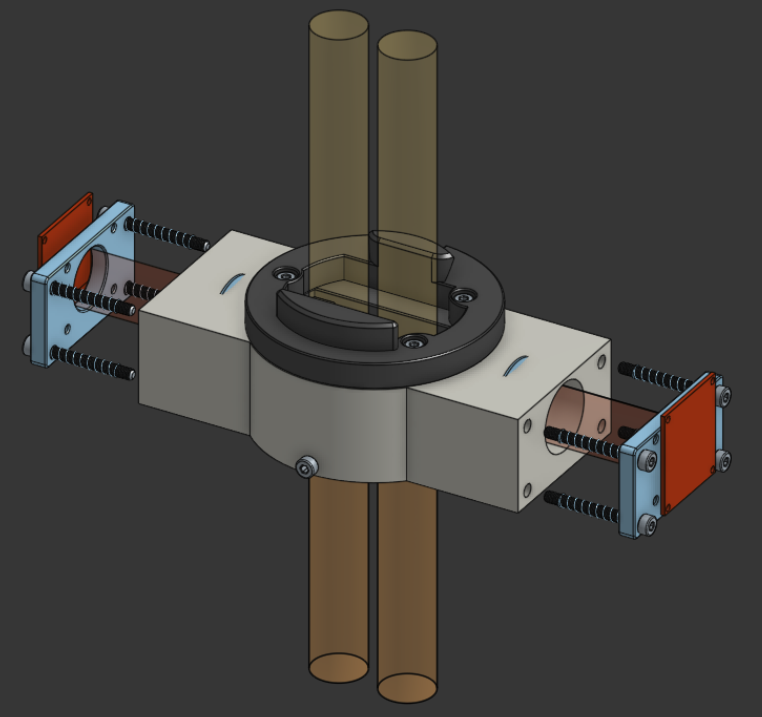
The CAD model is a concept visualization. It shows the optical paths and the mechanical layout, but not yet the final alignment, focus, clearances or image quality.
Optical Path
My whiteboard sketch for one channel, redrawn: OLED → lens → mirror → eyepiece.
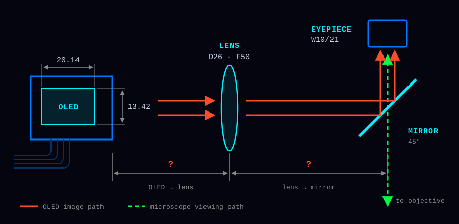
| Item | Value from the sketch | Note |
|---|---|---|
| OLED active area | 20.14 × 13.42 | unit still to confirm |
| Lens | D26, F50 | diameter 26 mm, focal length 50 mm |
| Eyepiece | W10/21 | original Zeiss eyepiece |
| OLED → lens | ? | not measured yet |
| Lens → mirror | ? | not measured yet |
For a first estimate, the thin lens equation links the object distance g (OLED to lens), the image distance b and the focal length f:
1/f = 1/g + 1/b
m   = -b/g
m is the lateral magnification. This estimates only the lens image. It does not include the eyepiece, the mirror alignment, aberrations or the full binocular system.
Still to verify
- OLED active area and its unit
- Lens diameter and focal length from the datasheet
- OLED-to-lens distance and the lens principal plane
- Folded path to mirror and eyepiece, mirror angle and clear aperture
- Both OLED channels match the left and right eyepiece paths
- Focus and image position on a physical prototype
Mono Beamsplitter Test
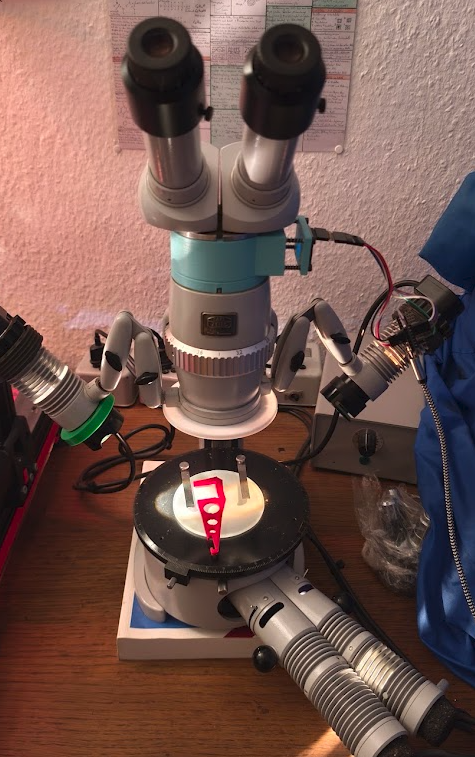
Before the stereo version, I tested a mono beamsplitter below the binocular head.
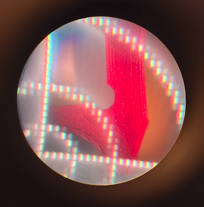
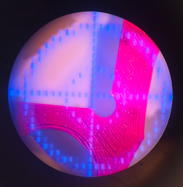
Two views through the eyepiece with a crosshair overlay:
| White crosshair | Blue crosshair |
|---|---|
 |
 |
Crosshair Firmware
The overlay comes from a small LVGL firmware (PlatformIO, LovyanGFX). It draws a red reticle on black: a horizontal and a vertical line and three concentric circles. The target controller is an ESP32-S3 Mini. The checked-in configuration still uses the old ESP32-S2 Mini with an ST7735S TFT, so check board and pins before flashing.
Next Steps
- Complete the optical calculation with measured distances
- Update the CAD model with verified dimensions
- Print and test the stereo prototype